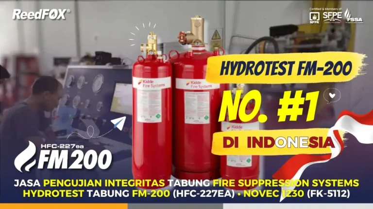
Kidde Fire Systems Fluoro-K clean agent suppression systems ECS-500 menawarkan tekanan pendorong yang lebih tinggi, yaitu 500 psi (35 bar). Sehingga memiliki kinerja yang lebih unggul jika dibandingkan dengan sistem Novec-1230 clean agent ECS 360 psi yang hanya memiliki tekanan 25 bar. Kidde Fire Systems Fluoro-K clean agent suppression systems adalah solusi pemadam kebakaran yang aman, kompetitif, dan hemat biaya.
Clean agent Fluoro-K karakteristiknya tidak berwarna, aroma yang ringan, dan tidak ada partikulat atau residu berminyak yang memungkinkan gangguan bisnis pasca pelepasan gas. Dari sudut pandang lingkungan, Fluoro-K tidak memiliki potensi penipisan ozon, dan terurai di atmosfer kurang dari lima hari. ECS-500™ dan ADS™ telah memiliki persetujuan global, pilihan ukuran, serta kapasitas, menjadikan Kidde Fluoro-K sebagai pilihan solusi pemadaman kebakaran yang cocok untuk Anda.
Hazard Protection
An ECS-500 or ADS system using Fluoro-K can be designed to cover a single hazard or multiple hazards from a common cylinder bank. Wherever possible, a fully connected reserve bank of cylinders is highly recommended to ensure your assets remain fully protected, even after a discharge of the main bank.
Single Zone System
The following figure depicts an example of an ECS-500 system using Fluoro-K Clean Agent configured to protect one hazard.

Multi Zone System
Multi zone systems can protect multiple hazards with one bank of cylinders. Multi zone systems require the use of one 2-way pneumatically operated selector valves for each zone protected.The following depicts an example of a multizone setup which protects 3 separate hazard zones. Pressure to operate the selector valves is provided by a Nitrogen pilot cylinder.

| Item | Description |
|---|---|
| 1 | Agent Storage Cylinder/Valve Assembly |
| 2 | Selector Valve |
| 3 | 108 cu. in. Nitrogen Pilot Cylinder |
| 4 | Back-Plate Manifold which includes the following: |
| 5 | Back-Plate Manifold Pressure Regulator |
| 6 | Back-Plate Manifold Solenoid |
| 7 | Back-Plate Manifold Hose (Order 1 additional hose per hazard.) |
Component Description
Cylinder and Valve Assemblies
The Fluoro-K clean agent in the ECS-500 or ADS systems is stored in welded steel cylinders compliant with ISO 9809-2 and certified to DOT. System activation and gas discharge is controlled via a pressure controlling valve. The cylinder or valve is equipped with a safety burst disc in compliance with DOT requirements. Cylinder sizes are available to suit floor space and agent quantity needs.
- ECS-500: 10, 20, 40, 70, 125, 200, 350, 450, 600, 900, and 1100 lb
- ADS: 200, 350, 450, 600, and 900 lb.
Cylinder shells are painted red for easy identification and include agency markings where applicable.
When shipped, cylinder-valve assemblies include an anti-recoil cap and a Safety Transport cap as a safety feature designed to prevent uncontrolled, accidental discharge.

Note: All cylinders in a system must be of equal size and pressure.

Cylinder Mounting Straps
Use the Cylinder Mounting straps to mount the cylinders in a vertical position. Cylinder straps are available for all size cylinders.

Note: For the 450 lb cylinders and for all Marine applications, 2 straps are required.
Cylinder Supervisory Pressure Switch
Cylinder supervisory pressure switches are intended to detect a fall in pressure in a clean agent or Nitrogen filled driver cylinder. The cylinder supervisory pressure switch can be wired for either normally open or normally closed operation, depending on installation requirements.


Gambar 4. Cylinder Supervisory Pressure Switch
Liquid Level Indicator
The Liquid Level Indicator (LLI) consists of a hollow stainless steel tube inserted into a special fitting in the top of the 125, 200, 350, 450, 600, 900 or 1100 lb (57, 91, 159, 205, 272, 408, or 499 kg) agent cylinder. The LLI is provided with a graduated flexible tape that senses the position of a toroidal magnet encased within an internal float riding on the liquid surface. The graduations on the tape indicate the liquid level within the cylinder.
Control Heads
Control heads provide various means of actuation for the agent or driver/pilot cylinder. A variety of control heads are available including:
- Electric
- Electric/Cable
- Pressure
- Lever
- Cable


Manifold El-Check Valves
Manifold El-Checks valves are installed at the discharge manifold in a multiple cylinder arrangement to allow removal of an agent cylinder from the manifold while still retaining a closed system. El-Check valves are available in 1-1/2, 2, and 3 in. sizes.
Note: El-Checks are to be installed at system manifold in vertical direction.

Discharge Hoses and Valve Outlet Adapters
Use the Flexible Discharge hose to connect the agent cylinder to the discharge piping.
While the 1-1/2 and 2 in. hoses are rubber covered with wire braided reinforcements, the 3 in. discharge hose has a stainless steel braid and roll-groove fittings.

As an alternative to the Flexible Discharge hose, Valve Outlet adapters are available in 1-1/2, 2, and 3 in. sizes.


Selector Valves
In multi-hazard applications, selector valves route agent from a central cylinder bank to the specific hazard where fire has been detected. Selector valve actuators operate pneumatically using agent pressure routed from the manifold via a pressure regulator on the back-plate manifold and the respective back-plate solenoid valve.

For NEMA 4 rated selector valves, solenoids can be ordered pre-installed on a back plate for two through five hazards. The solenoids are mounted on the back plate with tamper proof screws and cannot be removed. (Lihat Gambar 1.)
Lockout Valve
A lockout valve is a manually operated valve installed between the agent manifold and the discharge pipe network leading to the protected area. Lockout valves should be locked in the closed position to prevent agent from discharging into the protected area when the system or the protected space are being maintained.
Lockout valves can be installed at the end of the manifold or, if a common manifold protects multiple hazards, downstream of each selector valve. Lockout valves include a limit switch. The limit switch must be wired to the control panel to indicate a trouble if the valve is closed.

Agent Discharge Nozzles
The ECS-500 and ADS hardware includes nozzles with 360° and 180° discharge patterns which can be mounted in either upright or pendant style. The number and size of the orifice on each nozzle is custom calculated using the Flow Calculation Software Suite version 4.0 and higher.


Safety Outlets
Safety Outlets are designed to protect against over-pressurization in closed sections of discharge pipework, i.e., manifolds. The hardware offer includes a Safety Outlet rated for agent pressures and one rated for Nitrogen pilot line pressures.

Pressure Switch
The pressure operated switch uses the pressure of the discharging agent for activation and must be connected to the distribution piping. The agent actuates a pressure operated stem which toggles the electrical switch. Each switch can also be operated manually by pulling up on the stem. These switches are used to annunciate alarms, shut down ventilation, and turn on electrical automatic dampers or other electrical equipment. Each pressure switch must be manually reset, by pushing down on the stem to return the switch to the set position. The minimum operating pressure required is 50 PSI.The toggle on the pressure switch can be set to either N.O. to close or N.C. to open contact transfer upon operation.

Pressure Operated Trip
The pressure operated trip, is connected to the distribution piping and utilizes agent pressure for actuation. The agent pressure displaces a spring-loaded piston to disengage a holding ring from the stem connected to the piston.

Main & Reserve Systems
ECS-500 and ADS platform configurations support a ‘reserve’ bank of cylinders, equal in quantity and size to the main bank. A reserve system can minimize downtime and prevent service interruption in case of a discharge. A reserve system is also recommended when using selector valves and when downtime cannot be tolerated.
The system with main and reserve cylinders are connected to Suppression Control Panel through a Main/Reserve Transfer Switch.
Main & Reserve Transfer Switch:
The main & reserve transfer switch, is installed on systems having main and reserve cylinders. Placing the switch in either the “main” or “reserve” position provides uninterrupted fire protection capability during system maintenance or in the event of a system discharge.

Baca juga: Instalasi Pipa Clean Agent Gas Fire Suppression Systems
Control Panel
For systems covering a single zone, an AEGIS™ 2.0 control unit is typically ideal. Multi zone systems using selector valves require an addressable control unit such as the ARIES-SLX single loop or ARIES-MLX multi-loop.
Note: The use of a control unit that lacks compatibility listing by Kidde Fire Systems and relevant listing/approval agencies, voids all warranties whether expressed or implied. Refer the Terms & Conditions of Sale document.
Flow Calculation Software Version 4.0
Using the parameters listed below the Flow Software calculates pressure drops, pipe sizes, orifice sizes and vent area requirements:
- Agent selection
- Platform (ECS-500 or ADS) selection
- Cylinder Size
- Nozzle Selection 180º/360º
- Single Zone/Multi Zone Systems through 2 Way Selector valves
Fluoro-K™ Fire Suppression Clean Agent
Fluoro-K™ adalah bahan pemadam api berbahan dasar fluorinated ketone yang tidak berwarna, tidak menghantarkan listrik dan memiliki aroma yang ringan. Fluoro-K memadamkan api dengan cara menyerap panas kebakaran namun tetap mempertahankan kadar oksigen di udara.
Hal ini memungkinkan manusia untuk melihat dan bernapas, sehingga memungkinkan mereka untuk keluar ruangan yang terbakar dengan aman.
Penggunaan Fluoro-K telah mendapat persetujuan dari aturan program United States Environmental Protection Agency (EPA) Significant New Alternatives Policy (SNAP) untuk penggunaan di ruangan yang berpenghuni.
Meskipun bahan tersebut kita anggap aman dan tidak beracun bagi manusia (dengan tingkat konsentrasi design pada sebagian besar kebakaran), pertimbangan keselamatan tertentu harus selalu kita perhatikan saat menggunakan dan menangani bahan tersebut.
Pelepasan bahan dapat menimbulkan bahaya bagi manusia karena produk penguraian yang mereka hasilkan jika bahan tersebut terpapar api atau permukaan panas lainnya. Paparan terhadap agent umumnya tidak begitu memprihatinkan dibandingkan paparan terhadap produk dekomposisi. Paparan yang tidak perlu terhadap bahan atau produk penguraian harus kita hindari.
Agent Fluid Physical Properties
| Chemical Formula | CF3CF2C(O)CF(CF3)2 |
| NFPA Reference | FK-5112 (Dodecafluoro-2-methylpentan-3-one) |
| Molecular Weight | 316.04 |
| Freezing Point | -162.4°F (-108°C) |
| Boiling Point at 1 Atm. | 120.6°F (49.2°C) |
| Critical Temperature | 335.6°F (168.7°C) |
| Critical Density | 39.91 lb./ft.3 (639.1 kg/m3) |
| Critical Pressure | 270.44 PSIA (1865 kPa) |
| Critical Volume | 0.0251 ft.3/lbm (494.5 cc/mole) |
| Ozone Depletion Potential | 0 |
| Global Warming Potential | 1 |
Agent Fluid Toxicity Properties
| NOAEL (No Observable Adverse Effect Level) | 10.0% |
| LOAEL (Lowest Observable Adverse Effect Level) | >10.0% |
Bagaimanapun hindarilah paparan yang tidak perlu terhadap clean agent sesuai dengan persyaratan NFPA 2001. Oleh karena itu, setelah pengoperasian pre-discharge sistem alarm, semua personel harus segera keluar dari ruangan. Dalam keadaan apa pun personel tidak boleh menetap di dalam ruangan yang mengalami kebakaran.
Bahkan dalam keadaan yang sangat tidak mungkin terjadi, misalnya ketika sistem Fluoro-K clean agent tiba-tiba discharge ke dalam ruangan, maka semua personel harus berjalan dengan tenang dan tertib menuju pintu keluar untuk meninggalkan ruangan.
United States Environmental Protection Agency (U.S. EPA) telah menyetujui sensitisasi jantung terhadap Fluoro-K melalui evaluasi protokol pengujian. Program EPA SNAP mengklasifikasikan bahwa Fluoro-K dapat mereka terima untuk kita gunakan sebagai gas clean agent total flooding di dalam ruangan yang berpenghuni, namun dengan batasan tertentu.
Anda bisa melihat aturan program SNAP atau NFPA 2001 untuk informasi lebih lanjut. Fluoro-K telah dinilai dapat diterima oleh US EPA untuk penggunaan di dalam ruangan yang berpenghuni, bila penggunaannya sesuai dengan panduan NFPA 2001. Sesuai dengan NFPA 2001, izin rancangan Fluoro-K hanya boleh untuk penggunaan dengan konsentrasi uap zat hingga 10% volume di udara.
Meskipun Fluoro-K memiliki toksisitas yang dapat kita abaikan dalam konsentrasi yang kita perlukan untuk memadamkan sebagian besar kebakaran, pertimbangan keselamatan tertentu harus kita perhatikan saat mengaplikasikan dan menangani bahan tersebut.
Misalnya, cairan zat adalah cairan pada suhu ruang dan telah kita beri tekanan pendorong dengan nitrogen. Setelah pelepasan ke tekanan atmosfer (misalnya, dari nozzle), cairan akan menguap dengan cepat pada suhu rendah. Oleh karena itu, nozzle harus kita tempatkan secara khusus untuk menghindari paparan langsung dengan personel.
Decomposition
Ketika Fluoro-K terpapar suhu yang tinggi, seperti yang mungkin terjadi pada bagian permukaan nyala api, produk dekomposisi termal yang berbahaya (asam halogen) akan tercipta. Jika Fluoro-K discharge dan habis dalam waktu 10 detik atau kurang, maka api akan padam dengan cepat dan jumlah produk sampingan yang kebakaran hasilkan juga akan cuma sedikit.
Pembersihan
Fluoro-K adalah gas cair yang bersih dan tidak meninggalkan residu, sehingga menghilangkan biaya pembersihan setelah kebakaran dan meminimalkan downtime yang mahal. Sebagian besar material seperti baja, baja tahan karat, aluminium, kuningan, dan logam lainnya serta plastik, karet, dan komponen elektronik lainnya tidak terpengaruh oleh paparan Fluoro-K.
Approvals
The agent fluid complies with the NFPA Standard 2001, Standard for Clean Agent Fire Extinguishing Systems, EPA SNAP Program, (Significant New Alternate Policy), Underwriters Laboratories, Inc. (UL) FM Approvals (FM).
| Agent | Industrial Approval | Marine Approval |
|---|---|---|
| Kidde Fire Systems Fluoro-K™ Fire Suppression Clean Agent | UL, ULC, FM | UL |
Use
Kidde Fire Systems Fire Suppression Systems designed for use with the agent are designed to extinguish fires in specific hazards or equipment located where an electrically non-conductive agent is required, where agent cleanup creates a problem, where extinguishing capability with low weight is a factor and where the hazard is normally occupied by personnel. The agent fluid is an acceptable alternative to Halon, HFC-227ea, HFC-123, and HFC-125 and is approved by the EPA and NFPA for use in fire suppression systems.
Compatibility
| System | Industrial Approval | Marine Approval |
|---|---|---|
| ECS-500™ with Fluoro-K™ Fire Suppression Clean Agent | UL, ULC, FM | UL |
| ADS™ with Fluoro-K™ Fire Suppression Clean Agent | UL, ULC, FM | UL |
| ECS™ 360 with Fluoro-K™ Fire Suppression Clean Agent* | UL, ULC, FM | UL |
NFPA Minimum Design Concentrations for FK5112 Fluoro-K™ Fire Suppression Clean Agent
| Class A | 4.50 |
| Class B (n-Heptane) | 5.85* |
| Class B (Ethyl alcohol) | 7.02* |
| Class C with Voltage <480 V | 4.52 |
| Class C with Voltage ≥480 V | For voltages ≥480 volts that remain powered during and after discharge, the MDC shall be determined by testing, as necessary, and a hazard analysis. |
FM Global Class C Concentration Values
Per the FM Global Property Loss Prevention Data Sheet 4-9, Interim Revision July 2021, the Class C Fires Minimum Design Concentrations for Fluoro-K Fire Suppression Clean Agent are as follows:
| Class of Fire | Minimum Design Concentration |
|---|---|
| Class C with Voltage ≤ 480 V | 4.52 |
| Class C with Voltage > 480 V | 10 |
Note: The Minimum Design Concentration for Class C fires with voltages greater than 480 volts meets or exceeds the EPA Accepted LOAEL and NOAEL for the agent. Using this high of an MDC requires use of the following:
FM Global Class C Fires Minimum Design Concentrations for Fluoro-K Fire Suppression Clean Agent.
- Pneumatic Time Delays
- Pneumatic Sirens
- Signs
- Lockout Valves
Pilihan hardware profile – sesuai dengan berbagai jenis aplikasi:
- Kesesuaian untuk berbagai jenis kebakaran memperluas cakupan aplikasi:
– Class A, surface fires, MDC: 4.5%
– Class B, hydrocarbon fires (n-Heptane), MDC: 5.85%
– Class C, electrical fires under 480V, MDC: 4.52% - Berbagai pilihan tekanan pendorong untuk aliran gas dengan jarak yang lebih jauh:
– ECS-500™ dengan tabung yang berisi tekanan pendorong hingga 35 bar (500 psi).
– ADS™ dengan tabung pendorong Nitrogen terpisah yang tekanan hingga 125 bar (1800 psi). - Kapasitas tabung untuk menyesuaikan luas lantai penyimpanan dan kebutuhan gas:
– ECS-500™: Tersedia mulai tabung kapasitas 40, 70, 125, 200, 350, 450, 600, 900, hingga 1100 lbs.
– ADS™: Tersedia mulai tabung kapasitas 200, 350, 450, 600, hingga 900 lbs. - Fleksibilitas desain & instalasi pipa dengan beragam jenis nozzle:
– 180° (Pendant or upright)
– 360° (Pendant or upright)
Aman bagi lingkungan
- Zero Ozone Depletion Potential (ODP).
- Global Warming Potential (GWP) kurang dari 1.
Rentang suhu yang luas
- Rentang suhu antara 32° hingga 130°F (0° hingga 54°C),
cocok untuk area yang panas maupun dingin.
Sertifikasi yang diterima di seluruh dunia
- Transportasi: DOT Approved.
- Performa produk: UL Listed, FM Approved.
Cocok untuk berbagai lokasi vital
- Data center, server.
- Rumah sakit, fasilitas medis.
- Perpustakaan dan arsip.
- Museum, pameran budaya.
- Petroleum, oil & gas.
- Pabrik farmasi.
- Fasilitas telekomunikasi.
- dll.
Daftar Komponen FK-5112 Fluoro-K Clean Agent Suppression
| Description | Part Number |
|---|---|
| Cylinder, 500 psi, 10 lb. (4.5 kg), 1.5 in. Valve, No LLI | 45-550010-901 |
| Cylinder, 500 psi, 20 lb. (9 kg), 1.5 in. Valve, No LLI | 45-550020-901 |
| Cylinder, 500 psi, 40 lb. (18 kg), 1.5 in. Valve, No LLI | 45-550040-901 |
| Cylinder, 500 psi, 70 lb. (32 kg), 1.5 in. Valve, No LLI | 45-550070-901 |
| Cylinder, 500 psi, 125 lb. (57 kg), 1.5 in. Valve, with LLI | 45-550121-901 |
| Cylinder, 500 psi, 200 lb. (91 kg), 2 in. Valve, with LLI | 45-550201-901 |
| Cylinder, 500 psi, 350 lb. (159 kg), 2 in. Valve, with LLI | 45-550351-901 |
| Cylinder, 500 psi, 450 lb. (205 kg), 2 in. Valve, with LLI | 45-550451-901 |
| Cylinder, 500 psi, 600 lb. (272 kg), 3 in. Valve, with LLI | 45-550601-901 |
| Cylinder, 500 psi, 900 lb. (408 kg), 3 in. Valve, with LLI | 45-550901-901 |
| Cylinder, 500 psi, 1100 lb. (499 kg), 3 in. Valve, with LLI | 45-551101-901 |
| Description | Part Number |
|---|---|
| 200 lb. Capacity Cylinder and Valve Assembly, 2 in. Valve, with LLI | 45-500201-901 |
| 350 lb. Capacity Cylinder and Valve Assembly, 2 in. Valve, with LLI | 45-500351-901 |
| 450 lb. Capacity Cylinder and Valve Assembly, 2 in. Valve, with LLI | 45-500451-901 |
| 600 lb. Capacity Cylinder and Valve Assembly, 3 in. Valve, with LLI | 45-500601-901 |
| 900 lb. Capacity Cylinder and Valve Assembly, 3 in. Valve, with LLI | 45-500901-901 |
| Description | Part Number |
|---|---|
| Agent Cylinder Supervisory Pressure Switch | 06-118262-001 |
| Agent Cylinder ATEX Supervisory Pressure Switch | 06-118537-001 |
| Nitrogen Driver and Pilot Cylinder Supervisory Pressure Switch | 85-111540-001 |
| Nitrogen Driver and Pilot Cylinder ATEX Supervisory Pressure Switch | 85-111540-100 |
| Description | Part Number |
|---|---|
| Electric Control Head Kit, Includes: Control Head Monitor, P/N 85-100000-100 Electrical Control Head, 24 VDC, P/N WK-890181-200 | 85-890181-200 |
| Stackable Electric Control Head Kit, Includes: Control Head Monitor, P/N 85-100000-100 Lever Operated Control Head (with Black Lever), P/N WK-870652-000 Electrical Control Head, 24 VDC, Stackable, (Ex. Proof), P/N: 82-486500-010 | 85-486500-010 |
| Electric and Cable Operated Control Head (Explosion Proof) Kit, Includes: Control Head Monitor, P/N 85-100000-100 Electrical and Cable Operated Control Head, 24 VDC, (Ex. Proof), P/N WK-897494-000 | 85-897494-000 |
| Electric and Cable Operated Control Head Kit, Includes: Control Head Monitor, P/N 85-100000-100 Electrical and Cable Operated Control Head, 24 VDC, P/N: 81-895630-200 | 85-895630-200 |
| Control Head Monitor | 85-100000-100 |
| Cable Operated Control Head | 81-979469-000 |
| Lever Operated Control Head (with Black Lever) | WK-870652-000 |
| Lever/Pressure Operated Control Head (with Black Lever) | 82-878751-000 |
| Pressure Operated Control Head | 82-878737-000 |
| Pressure Operated Control Head, Stackable | 82-878750-000 |
| Description | Part Number |
|---|---|
| Flexible Discharge Hose, 1-1/2 in. dia., 24 in. length, for use with 10 to 125 lb (4.5 kg to 57 kg) Cylinders | WK-283898-000 |
| Flexible Discharge Hose, 2 in. dia., 31 in. length, for use with 200 to 350 lb (91 kg to 159 kg) Cylinders | WK-283899-000 |
| Flexible Discharge Hose, 3 in. dia., 54 in. length, for use with 600, 900, and 1100 lb (243, 408, and 499 kg) Cylinders | 06-118225-001 |
| Valve Outlet Adapter, 1-1/2 in. (38 mm), 10 to 125 lb (4.5 kg to 57 kg) Cylinders | WK-283904-000 |
| Valve Outlet Adapter, 2 in. (51 mm), 200 to 350 lb (91 kg to 159 kg) Cylinders | WK-283905-000 |
| Valve Outlet Adapter, 3 in. (76 mm) Grove to NPT Thread Adapter, 600, 900 lb and 1100 lb (243, 368 and 499 kg) Cylinders | 70400133 |
| Manifold El-Check, 1-1/2 in. (38 mm) | WK-877690-150 |
| Manifold El-Check, 2 in. (51 mm) | WK-877690-200 |
| Manifold El-Check, 3 in. (76 mm) | WK-877690-300 |
| Safety Outlet, Agent | 82-844346-000 |
| Safety Outlet, Nitrogen | 81-803242-000 |
| Pressure Operated Switch | 81-486536-000 |
| Pressure Operated Switch, Explosion Proof | 81-981332-000 |
| Pressure Operated Siren | 90-981574-001 |
| Nitrogen Time Delay for use with 108 cu. in. Pilot Cylinder (nominal 34 sec. delay) | 81-871072-001 |
| Nitrogen Time Delay for use with 108 cu. in. Pilot Cylinder (nominal 61 sec. delay) | 81-871072-002 |
| Nitrogen Time Delay for use with 1040 cu. in. Pilot Cylinder (nominal 35 sec. delay) | 81-871072-003 |
| Nitrogen Time Delay for use with 1040 cu. in. Pilot Cylinder (nominal 68 sec. delay) | 81-871072-004 |
| Pressure Operated Trip | 81-874290-000 |
| Discharge Indicator, 1/2 in. NPT (Aluminum) | 81-875553-000 |
| Discharge Indicator, 3/4 in. NPT (Brass) | 81-967082-000 |
| Main-to-Reserve Transfer Switch | 85-802398-001 |
| Description | Part Number |
|---|---|
| 1 in. Selector valve, NPT, 116-145 psi Actuator, NEMA 4 Rated Solenoid | 85-100025-100 |
| 1 1/2 in. Selector valve, NPT, 116-145 psi Actuator, NEMA 4 Rated Solenoid | 85-150025-150 |
| 2 in. Selector valve, NPT, 116-145 psi Actuator, NEMA 4 Rated Solenoid | 85-200025-200 |
| 3 in. Selector valve, Grooved, 116-145 psi Actuator, NEMA 4 Rated Solenoid | 85-300025-300 |
| 4 in. Selector valve, Grooved, 116-145 psi Actuator, NEMA 4 Rated Solenoid | 85-400025-400 |
| Description | Part Number |
|---|---|
| 1 in. Selector valve, NPT, 116-145 psi Actuator, NEMA 7 Rated Solenoid | 85-100724-100 |
| 1 1/2 in. Selector valve, NPT, 116-145 psi Actuator, NEMA 7 Rated Solenoid | 85-150724-150 |
| 2 in. Selector valve, NPT, 116-145 psi Actuator, NEMA 7 Rated Solenoid | 85-200724-200 |
| 3 in. Selector valve, Grooved, 116-145 psi Actuator, NEMA 7 Rated Solenoid | 85-300724-300 |
| 4 in. Selector valve, Grooved, 116-145 psi Actuator, NEMA 7 Rated Solenoid | 85-400724-400 |
| Description | Part Number |
|---|---|
| Back-Plate Manifold with Solenoids – 2 Area, Selector Valve Control, 116 psi | 01-3508-0002 |
| Back-Plate Manifold with Solenoids – 3 Area, Selector Valve Control, 116 psi | 01-3508-0003 |
| Back-Plate Manifold with Solenoids – 4 Area, Selector Valve Control, 116 psi | 01-3508-0004 |
| Back-Plate Manifold with Solenoids – 5 Area, Selector Valve Control, 116 psi | 01-3508-0005 |
| Back-Plate Manifold Hose | 01-3273-1200 |
| 1/8 in. NPT Male to 1/4 in. Male BSPP Adapter | 85-025125-000 |
| 1 in. BSPT (M) to NPT (F) Adapter (2 required per valve, entry/exit) | 01-3711-3000 |
| 1 1/2 in. BSPT (M) to NPT (F) Adapter (2 required per valve, entry/exit) | 01-3711-4000 |
| 2 in. BSPT (M) to NPT (F) Adapter (2 required per valve, entry/exit) | 01-3711-5000 |
| Hose Adapter for For 1, 1-1/2 and 2 in. Selector Valves, Nipple 1/4 in. BSPP 60° x 1/4 in. BSPT M/M | 15-8662-0042 |
| Hose Adapter for For 3 and 4 in. Selector Valves, Nipple 1/4 in. BSPP 60° x 1/8 in. BSPT M/M | 15-8662-0041 |
| Pressure Regulator – 4351 psi to 116 psi | 01-6017-0000 |
| Description | Part Number |
|---|---|
| 1 in. Lockout Valve, NPT, NEMA 4 Rated Switch | 85-100210-101 |
| 1 1/2 in. Lockout Valve, NPT, NEMA 4 Rated Switch | 85-150210-151 |
| 2 in. Lockout Valve, NPT, NEMA 4 Rated Switch | 85-200210-201 |
| 3 in. Lockout Valve, Grooved, NEMA 4 Rated Switch | 85-300210-301 |
| 4 in. Lockout Valve, Grooved, NEMA 4 Rated Switch | 85-400210-401 |
| Description | Part Number |
|---|---|
| 1 in. Lockout Valve, NPT, NEMA 7 Rated Switch | 85-100120-101 |
| 1 1/2 in. Lockout Valve, NPT, NEMA 7 Rated Switch | 85-150120-151 |
| 2 in. Lockout Valve, NPT, NEMA 7 Rated Switch | 85-200120-201 |
| 3 in. Lockout Valve, Grooved, NEMA 7 Rated Switch | 85-300120-301 |
| 4 in. Lockout Valve, Grooved, NEMA 7 Rated Switch | 85-400120-401 |
| Description | Part Number |
|---|---|
| Liquid level indicator for use on 125 lb (57 kg) agent cylinders. | 85-235000-025 |
| Liquid level indicator for use on 200, 350, 600, and 1100 lb (81, 142, 243, and 499 kg) agent cylinders. | 85-235000-037 |
| Liquid level indicator for use on 450 and 900 lb (182 and 408 kg) agent cylinders. | 85-235000-042 |


