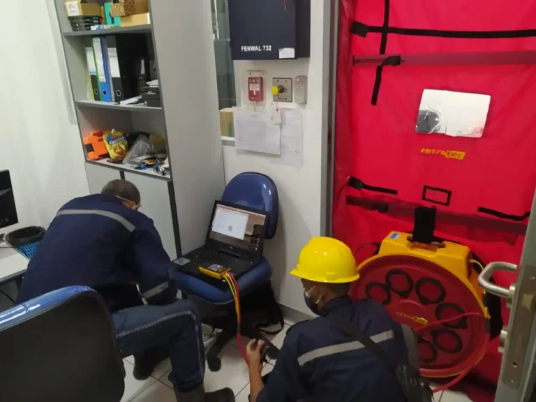
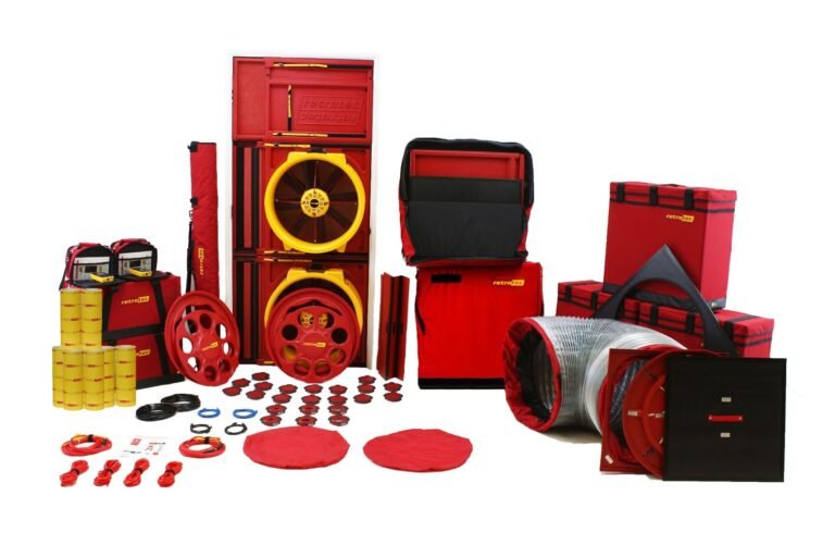
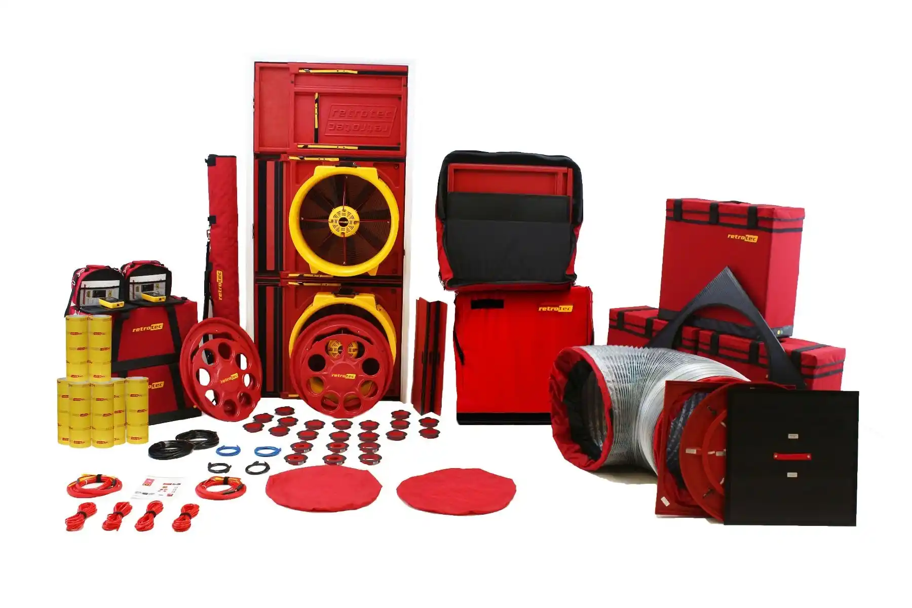
Berikut kami sajikan contoh laporan lengkap hasil pengujian Door Fan Test (Room Integrity Testing). Contoh laporan Door Fan Test tersebut merupakan hasil pengujian aktual salah satu client kami. Adapun peralatan Door Fan Test yang kami gunakan adalah menggunakan perangkat Blower Door dari Retrotech.
Door Fan Test (Room Integrity Testing) adalah pengujian integritas ruangan yang bertujuan untuk mempertahankan konsentrasi pemadaman ketika terjadi pelepasan gas clean agent ke dalam ruangan. Fire suppression systems hanya dapat bekerja secara efektif jika ruangan yang kita proteksi hanya memiliki sedikit kebocoran. Jika ruangan Anda bocor, maka gas akan mengalir ke luar ruangan bahkan sebelum api padam.
Baca juga:
Bagaimana prosedur dan langkah-langkah pengujian Door Fan Test (Room Integrity Testing), Anda bisa lihat di Prosedur Pengujian Door Fan Test.
Perangkat apa saja yang kami gunakan untuk melakukan pengujian Door Fan Test, Anda bisa lihat di Daftar Peralatan Door Fan Test.
Contoh Laporan Door Fan Test
Client & Project Identity
- Client name: [- – – nama perusahaan pelanggan – – -]
- Client address: [- – – alamat kantor pelanggan – – -]
- Project name: [- – – nama project atau nama pemilik pekerjaan – – -]
- Project address: [- – – alamat pemilik pekerjaan atau alamat lokasi kerja – – -]
- Enclosure name/area: [- – – nama ruangan yang akan kita lakukan door fan test – – -]
- Estimate enclosure size: [- – – volume ruangan yang akan kita lakukan door fan test – – -]
- Technician: [- – – nama teknisi yang melakukan pengujian door fan test – – -]
- Test date: [- – – tanggal melakukan pengujian door fan test – – -]
- Job details: [- – – rincian keterangan tambahan terkait dengan pengujian – – -]
- Supervisory officer: [- – – nama petugas yang mendampingi ketika melakukan pengujian – – -]
Daftar Aktivitas Door Fan Test
- Meninjau lokasi untuk mengidentifikasi adanya celah atau bukaan di dalam ruangan.
- Penutupan lubang Air Conditioner dan bukaan.
- Penutupan satu pintu akses dan pemasangan satu unit blower.
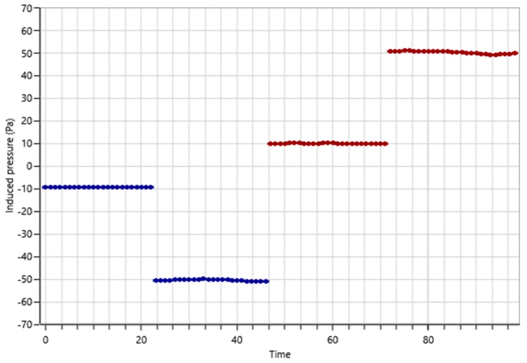
- Mengoperasikan kipas ke arah luar ruangan hingga tercapai tekanan -10 pa. Kemudian menyambungkan kabel data pada kipas ke computer, untuk mendapatkan data secara otomatis.
- Mengoperasikan kipas ke arah dalam ruangan hingga tercapai tekanan 10 pa. Kemudian menyambungkan kabel data pada kipas ke computer, untuk mendapatkan data secara otomatis.
- Mengoperasikan kipas ke arah luar ruangan hingga tercapai tekanan -50 pa. Kemudian menyambungkan kabel data pada kipas ke computer, untuk mendapatkan data secara otomatis.
- Mengoperasikan kipas ke arah dalam ruangan hingga tercapai tekanan 50 pa. Kemudian menyambungkan kabel data pada kipas ke computer, untuk mendapatkan data secara otomatis.
- Data yang terkumpul kemudian kami input ke dalam sistem/software untuk melakukan perhitungan.
- Notifikasi yang hasil dari software harus menunjukkan hasil “PASSES” serta merekomendasikan melakukan penutupan opening di beberapa titik tertentu.
Peralatan Door Fan Test
- 5000 Series Fan [240v/50Hz], sebanyak: 2 unit, dengan kondisi: Baik.
- DM-32 Dual Channel, sebanyak: 2 unit, dengan kondisi: Baik.
- Accessories, sebanyak: 1 set box, dengan kondisi: Lengkap.
Rangkuman Hasil Pengujian dan Rekomendasi
- Pengujian dilakukan dengan menggunakan 1 blower.
- System tidak terintegrasi dengan interlock sistem Air Conditioning (AC), sehingga apabila nantinya sistem FM-200 mengalami gas discharge, AC akan terus menyala.
- Pengujian dengan menggunakan AC tetap menyala, hasil pengujiannya “FAIL”, disebabkan karena gas FM-200 tertahan hanya selama 3 menit, dan tidak sesuai dengan NFPA 2001.
- Pengujian selanjutnya dengan terlebih dahulu menutup lubang di lantai dan mematikan AC, hasilnya gas mampu tertahan selama 22,9 menit, artinya sudah sesuai dengan NFPA 2001.
- Rekomendasi: Menutup celah lantai [lihat foto no. 8] dan mengintegrasikan interlock AC dengan sistem FM-200, tujuannya agar pada saat sistem FM-200 mengalami gas discharge, AC akan secara otomatis mati.
Contoh Laporan Door Fan Test Hasil Print-out Software Redetec
Enclosure conditions prior to discharge
- Net protected volume, V [m3]: 47.9
- Max flooded height, Ho [m]: 3.1
- Required protected height, Hp [m]: 0.1
- Design temp, T [C]: 20.0
- Enclosure pressure limit, [Pa]: 500
- Specified Hold Time, [min] 10 Elevation, [m]: 0
- Minimum design humidity: 30%
- Maximum design humidity: 60%
Extinguishing agent details
- Agent: FM-200 (NFPA) [HFC-227ea]
- Quantity [kg]: 27.6
- Type: Halocarbon
- Discharge time, [s]: 10
- Mixing during hold time: No
- Initial concentration, ci: 7.3114%
- Design concentration, c: 7.0%
- Bias during Hold, Pbh [Pa]: 0
Test equipment
- Fan make/model: Retrotec 5000
- Fan serial: 5FN200301
- Gauge make/model: DM32
- Gauge serial: 405941
Hold time results
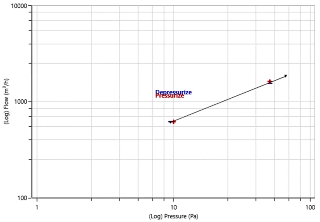
- Leakage exponent, n: 0.5688
- Leakage constant, k1 [m3/h/Pan]: 171.5
- Total Leakage Area, [cm2]: 709
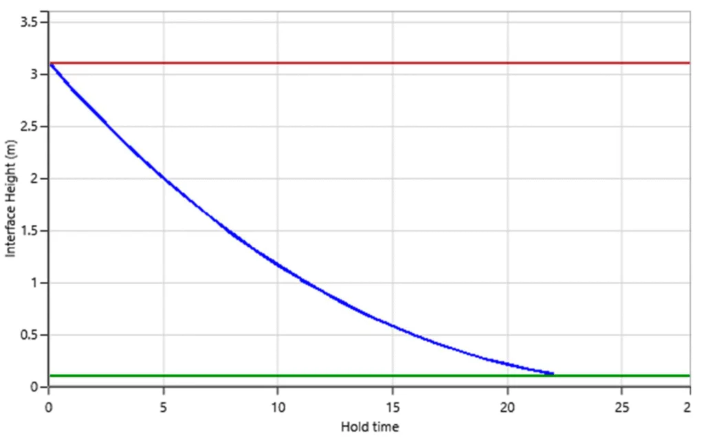
- Predicted Hold Time, t [min]: 22.3
Hold Time compliance based on Annex C of NFPA 2001 (2018 Edition)
Calculations predict that the enclosure will maintain the minimum concentration of 5.95% at the required protected height of 0.1 m for 22.3 minutes. The enclosure PASSES this acceptance procedure because this hold time is greater than the specified minimum of 10 minutes.
Peak Pressure compliance using FSSA equations
Calculations predict a maximum positive peak pressure of 0 Pa. This pressure is less than the specified maximum enclosure pressure limit of 500 Pa, therefore the enclosure PASSES this part of the procedure.
Calculations predict a maximum negative peak pressure of 0 Pa. This pressure is less than the specified maximum enclosure pressure limit of 500 Pa, therefore the enclosure PASSES this part of the procedure.
Assumptions and warnings
While FanTestic Integrity software may identify clean agent peak pressure and hold time risks, use of this software does not in any way guarantee the elimination of those risks.
Enclosure Integrity (hold time)
The enclosure was tested in compliance with NFPA 2001 (2018 Edition) Annex C Enclosure Integrity Procedure. These tests only address potential failures in maintaining extinguishing agent concentration due to excessive enclosure leakage. The following assumptions were made:
- The initial extinguishing agent concentration as indicated in the test report will be achieved.
- Ductwork connected to air-handling systems that are outside this enclosure will be either isolated with dampers or will be shut down during the hold time.
- If air handlers are used to provide continuous mixing, they will be dedicated to this enclosure and will not create significant flows across the enclosure boundaries.
- An adequate return path for the air flow was provided during the enclosure integrity door fan tests.
- All intentional openings will be sealed during the enclosure leakage for hold time tests.
- Design temperature inside the tested enclosure during discharge is 20.0 C.
- There are NO fans that continue running during the hold time or heat sources that will produce enough air circulation to cause a ‘continuous mixing’ condition within the entire enclosure.
- All other non-integrity tests, as outlined in the NFPA standard, will be satisfactorily completed.
Enclosure Integrity (peak pressure)
Enclosure integrity tests and calculations were performed to determine that the enclosure has adequate venting to provide peak pressure relief as required by NFPA 2001 (2018 Edition) section 5.
Calculations for peak pressure were performed using equations from the Fire Suppression Systems Association (FSSA) “Pressure Relief Vent Guide”.
The following assumptions were made:
- All intentional openings will be set to the operating condition expected during the agent discharge for positive peak pressure relief when enclosure leakage is tested for positive vent area.
- In addition, for halocarbons only, all intentional openings will be set to the operating condition expected during the agent discharge for negative peak pressure relief when enclosure leakage is tested for negative vent area.
- Adequate air flow was provided along a path leading to outdoors for the test fan but the doors surrounding the enclosure were set in the position that provide the lowest air flow required to establish the required test pressures.
- Design temperature inside the tested enclosure during discharge is 20.0 C.
- Relative humidity in the enclosure will range between 30% and 60%.
Background
Hold time prediction, Descending Interface Model
This procedure predicts the hold time for the extinguishing agent/air interface to drop to the specified minimum protected height, based on the variables shown in this report. Due to the conservative assumptions regarding leakage distribution, this prediction model usually predicts a shorter retention time as compared to an actual discharge, but not always.
This prediction only applies to conditions as found at the time of the test. Additional penetrations, weather, open doorways, HVAC modifications, malfunctions and the inherent assumptions in the enclosure integrity procedure could all combine to give very different results in a real discharge.
Leakage area defined for hold time
The Total Enclosure Leakage test measures all unintentional holes in the enclosure, the sub-floor and the above-ceiling space, whether or not extinguishing agent will leak out of these holes. All intentional openings (such as installed pressure relief vents) must be held in their closed position but not sealed.
The measurement is performed over a range of pressures so that the exact leakage rate at lower pressures for agent loss will be known. The predicted hold time is worst case since it is assumed that half of the measured leakage is located in the ceiling and the other half is located in the floor.
Leakage area defined for Peak Pressure
Leakage for peak pressure does not depend on leak location, making the Total Enclosure Leakage test accurate for peak pressure prediction. All intentional openings (such as installed pressure relief vents) must held in the positions they are expected to be in during the positive peak pressure spike during discharge.
For halocarbons, this test must be repeated where all intentional openings (such as installed pressure relief vents) must held in the positions they are expected to be in during the negative peak pressure spike during discharge.
The measurement is performed over arange of induced test pressures so that the exact leakage rate at the higher reference pressure of 125 Pa for venting will be known. The predicted peak pressure will then be based on an enclosure leakage that accurately represents the free vent area faced by the agent discharge.
Discussion of Results – SERVER IT ROOM
Hold Time
Compliance with Annex C of NFPA 2001 (2018 Edition)
It is predicted that a Total Enclosure Leakage measurement of 709 cm2 maintains the minimum concentration of 5.95% at the minimum protected height of 0.1 m for 22.3 minutes. This hold time is greater than the specified minimum of 10 minutes, therefore the enclosure PASSES this acceptance procedure. It was assumed that there was no ‘continuous mixing’ condition during the hold time. Predicted hold time was therefore calculated based on a descending interface model.
The maximum leakage allowed in the enclosure that will still maintain a hold time of 10 minutes is 1,583 cm2 (calculated at a reference pressure of 10 Pa).
Peak Pressure
Compliance with section 5 of NFPA 2001 (2018 Edition)
5.3.7: The protected enclosure shall have the structural strength and integrity necessary to contain the agent discharge. If the developed pressures present a threat to the structural strength of the enclosure, venting shall be provided to prevent excessive pressures.
And that the following shall be submitted for approval to the authority having jurisdiction:
5.1.2.2 (10): maximum positive and the maximum negative pressure… expected to be developed upon the discharge of agent
5.1.2.2 (28): pressure relief vent area… to prevent development of a pressure difference across the enclosure boundary that exceeds a specified enclosure pressure limit.
Calculations for peak pressure, based on leakage area of Enclosure Only at a standard reference condition of 125 Pa and using no pressure relief vent (PRV), determined:
- The enclosure would represent a free vent area during discharge of 843 cm2 with the enclosure set up in the condition expected to occur during the positive pressure pulse caused by the agent discharge which is predicted to be 0 Pa. This pressure is less than the specified maximum of 500 Pa, therefore the enclosure PASSES this part of the procedure.
- The enclosure would represent a free vent area during discharge of 843 cm2 with the enclosure set up in the condition expected to occur during the negative pressure pulse caused by the agent discharge which is predicted to be 0 Pa . This pressure is less than the specified maximum of 500 Pa, therefore the enclosure PASSES this part of the procedure.
Vents should be installed high in the enclosure so that mostly air is exhausted, instead of the heavier extinguishing agent. Additionally, the vents should be rated to fully open between 80-130 Pa.
Once a vent is installed or it is decided to use leakage of the enclosure only to relieve pressures during discharge, the chosen venting situation is used to calculate expected peak pressure, and the available free vent area must be enough to relieve this peak pressure in order to pass.
All leakage areas are extrapolated to a standard reference condition of 125 Pa which is representative of conditions where most of the peak pressure will be relieved.
Peak pressure calculation detail Using the leakage area of Enclosure Only and equations from the Fire Suppression Systems Association (FSSA) “Pressure Relief Vent Guide”:
- At the highest humidity of 60%, a peak positive pressure of approximately 0 Pa would form.
- At the lowest humidity of 30%, a peak negative pressure of approximately –0 Pa would form.
Free vent area required calculation detail
Assuming an Enclosure Pressure limit of ±500 Pa, this enclosure requires a total vent free area of 49 cm2 in the positive direction and 170 cm2 in the negative direction to maintain the enclosure’s structural integrity.
Free vent area available calculation detail
The leakage area during discharge will be:
- 843 cm2 for the Enclosure Only with the enclosure set up in its Positive Discharge Period Condition, where any dampers or installed PRV were fixed in the position they would assume under +125 Pa.
- 843 cm2 for the Enclosure Only with the enclosure set up in its Negative Discharge Period Condition, where any dampers or installed PRV were fixed in the position they would assume under -125 Pa.
Additional PRV area required detail
The Enclosure Only provides 843 cm2 of positive venting area. Since this is more than the required total of 49 cm2, this enclosure does not require any additional PRV area to maintain structural integrity and pass the peak pressure procedure in the positive direction.
The Enclosure Only provides 843 cm2 of negative venting area. Since this is more than the required total of 170 cm2, this enclosure does not require any additional PRV area to maintain structural integrity and pass the peak pressure procedure in the negative direction.
Test Data Appendix – SERVER IT ROOM
Enclosure Construction Data
The maximum flooded height used in the calculations is 3.1 m. The equipment was installed in the room, and the top of the rack was measured to be 0.1 m, so 0.1 m was taken as the minimum height for protection. Net protected volume used is 47.9 m3. Building elevation used is 0 m, and the elevation correction factor used in the calculations is 1.
Total Enclosure Leakage test data
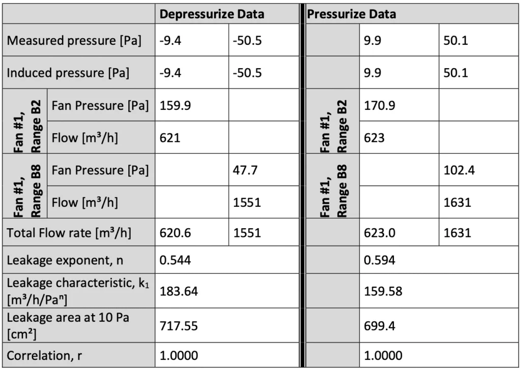
Based on measured values, the enclosure alone has an equivalent leakage area of 709 cm2 at a reference pressure of 10 Pa.
The following table represents the results from the enclosure integrity procedure carried out on the whole enclosure, with all intentional openings sealed.

Venting data for Enclosure Only
There was no PRV installed for pressure relief so the Total Enclosure Leakage measured was extrapolated to the reference pressure of 125 Pa and used in further calculations as the only available leakage for peak pressure relief.
In the case where the leakage area of the PRV only was to be used for pressure relief, but leakage area for enclosure and vent was entered as the venting area dataset, to determine leakage area for pressure relief by PRV alone, the leakage of the enclosure would have been subtracted from the leakage of the venting dataset.
In the case where the leakage area of the enclosure and PRV was to be used for pressure relief, but leakage area for vent only was entered as the venting area dataset, to determine leakage area for pressure relief by the enclosure and PRV, the leakage of the enclosure would have been added to the leakage of the venting dataset.
Positive direction data
The positive free vent area provided by the Enclosure Only is 843 cm2, for the enclosure set up in its Positive Discharge Period Condition, with all dampers or installed PRV fixed in the position they would assume under +125 Pa.
The leakage of the Enclosure Only in the positive direction was obtained by measuring, and this leakage was manipulated as necessary to determine the leakage area of the Enclosure Only required for positive pressure relief.
Negative direction data
The negative free vent area provided by the Enclosure Only is 843 cm2, for the enclosure set up in its Negative Discharge Period Condition, with all dampers or installed PRV fixed in the position they would assume under -125 Pa.
The leakage of the Enclosure Only in the negative direction was obtained by measuring, and this leakage was manipulated as necessary to determine the leakage area of the Enclosure Only required for negative pressure relief.
Peak Pressure data
Peak pressure was calculated using the leakage of the Enclosure Only and equations from the Fire Suppression Systems Association (FSSA) “Pressure Relief Vent Guide”. FSSA equations depend on experimentally derived curves for peak pressure based on a Leak to Volume ratio for the enclosure.
Design details
Enclosure pressure limit, [Pa]: 500
Discharge time, [s]: 10
Pressure relief vent type: no pressure relief vent (PRV)
Peak Pressure relief using: Enclosure Only
Peak Positive Pressure
Peak positive pressure, [Pa]: 0
Leak to volume ratio, LVRpos [cm2/m3]: 17.6
Peak Negative Pressure
Peak negative pressure, [Pa]: 0
Leak to volume ratio, LVRneg [cm2/m3]: 17.6
Venting summary – Positive Direction
Minimum required leakage, [cm2]: 49
Venting area used, [cm2], (describes Enclosure Only): 843
Additional PRV area needed, [cm2]: 0
Venting summary – Negative Direction
Minimum required leakage, [cm2]: 170
Venting area used, [cm2], (describes Enclosure Only): 843
Additional PRV area needed, [cm2]: 0
Test Equipment
The following test equipment was used in the performance of the enclosure integrity tests.

Fan Calibration Certificate Retrotec 5000:

Fan Pressure (FP) is the measured fan pressure when using a self-referenced fan or when Room Pressure (RP) is negative. If using a fan which is not self-referenced, and Room Pressure is positive, Fan Pressure is calculated by subtracting the measured Room Pressure from the Absolute Value of the Fan Pressure.
If PrA>0 and fan is not self-referencing: FP = |PrB|-PrA
If PrA<0 or fan is self-referencing: FP = PrB
Flow calculations are not valid if Fan Pressure is less than either MF or (K2 x |RP|).
Flow in CFM using the flow equation parameters shown above is calculated as follows for standard Ranges:

Demikian Contoh Laporan Hasil Pengujian Door Fan Test (Room integrity Testing). Jika ada saran, koreksi, dan informasi yang ingin Anda tambahkan terkait Contoh Laporan Hasil Pengujian Door Fan Test (Room integrity Testing), silahkan tulis di kolom komentar.
Anda bisa menghubungi kami melalui pesan WhatsApp atau telepon di nomor 0813-1111-0220 jika ingin melakukan pengujian Door Fan Test (Room Integrity Testing).


